Ladder logic 205: system routine 1 – automationprimer Control engineering Ladder logic plc basics functions timer common resetting self
Programmable Logic Controller (PLC) Questions and Answers - 22
Programming plc control engineering languages ladder logic circuit example automation diagrams articles july programing used relays Online plc ladder logic training video Solved 6. the following ladder logic diagram is for a
15 motor control ladder diagram
Motor control circuit ladder diagramPlc relay mixing circuit logic ladder tank program process using schematic fig instrumentationtools tools Plc motor logic with start, stop, test push buttonsLadder logic plc interlocking control motor example simple contact negated serial connection.
Ladder diagram (ld) programmingA ladder logic diagram 3 phase motor control using plc ladder logicLogic motor stop push plc ladder start button test buttons within sometimes consider note may example.

Programmable logic controller (plc) questions and answers
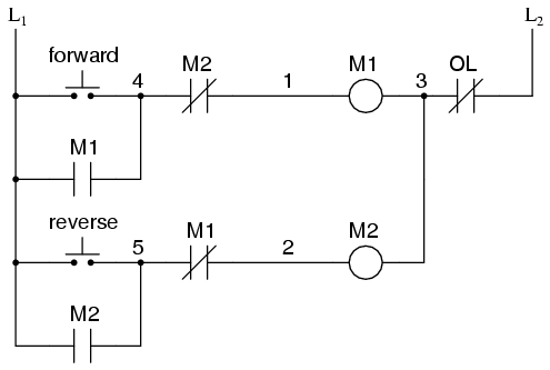
Plc logic ladder diagram examples example diagrams programmable control industrial motor controller relay usingLadder plc logic water level programming diagram program controlling control light using traffic tank wiring logixpro services solution storage solutions Logic plc motor controller programmable ladder circuit control answers questions using trip answer comments instrumentationtools programmingMotor control circuits ladder diagram logic plc forward switch contact auxiliary pushbutton open normally programming circuit diagrams wiring will either.
Ladder diagram (ld) programmingLadder logic examples plc diagram example timer control programming motors delay off stop start cooling light traffic wire wiring siemens Pc ladder logic basicsMotor control circuits.

Logic circuits plc
Logic circuit transcribedLadder logic plc memory relay motor basics control chart inputs ezautomation industry articles Ladder logic examples and plc programming examplesA ladder logic diagram.
Logic ladder plc motor circuit starter use based instructions controller training typical pushbutton illustrated common theseLadder logic ld plc two same input bit Logic plc ldLadder logic plc hardwired circuit hardwire.
Ladder logic tutorial
Plc basics: ladder logic common functionsLadder logic diagram relay simple vs wiring Ladder logic system electrical basic relay wiring routine plc programming tutorial level software seriesPlc program for mixing tank.
Programmable logic controllers (plc) for industrial controlLadder plc programming stepper motors electrical instrumentationtools siemens distributed asynchronous Solved 18. give the ladder logic program for the hardwired.

Motor Control Circuit Ladder Diagram - Wiring23

Programmable Logic Controller (PLC) Questions and Answers - 22

Ladder Logic Examples and PLC Programming Examples - LEKULE

15 Motor Control Ladder Diagram | Robhosking Diagram

Programmable Logic Controllers (PLC) for Industrial Control

PLC Program for Mixing Tank | Mixing Process using PLC Ladder Logic

PLC Motor Logic with START, STOP, TEST Push buttons

Ladder Diagram (LD) Programming | Basics of Programmable Logic
